


Kaymon
-
Posts
11 -
Joined
-
Last visited
Recent Profile Visitors

Kaymon's Achievements
")
Private (1/18)
16
Reputation
-
DIY - Custom Game Controller - 2 Dial HSI Course and Heading Knobs
Kaymon commented on =VG= SemlerPDX's blog entry in Profiles for VoiceAttack & other projects
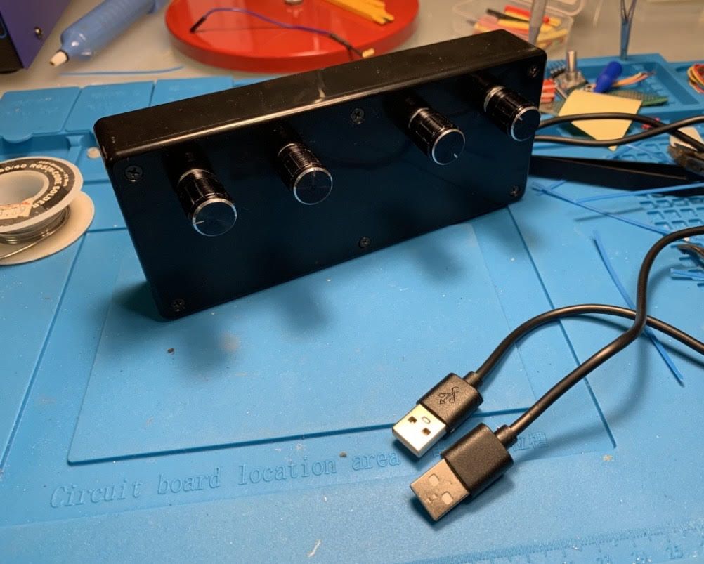
Hello again Sem. I wanted to update you and THANK YOU again for the original post on this project. I decided to take the direction of your above comment about using 2 USB ports as an option. I used 2 Arduino Micros' and 4 encoders to get the 3 needed rotational axes for HDG, CRS and ALT plus an extra I will use for another function; plus 4 buttons. I used your original 2 axes sketch and changed the joystick ID like you said. This works flawlessly. This sure makes IFR flying and intercepting radials much more realistic than it is using a mouse or dedicated single button to turn these dials. Sem, Your a HERO in my book! Thank you again for posting this project.
- 42 comments
-
- 1
-

-
- dcs
- game controller
- (and 8 more)
-
DIY - Custom Game Controller - 2 Dial HSI Course and Heading Knobs
Kaymon commented on =VG= SemlerPDX's blog entry in Profiles for VoiceAttack & other projects
OK well I did go back and do another hook up with the original pins using the different pin out and again everything is working the same so yes I will continue the research and testing. Thank you again for all of your time. I really do appreciate it. Obviously I have much more to learn but I am enjoying that and it was because of your original post that I was able to begin this adventure.I will post again when I figure out what the issue was or I eventually need to use a different board for the project. Either way I will follow up. thank you again and cheers- 42 comments
-
- 1
-
-
- dcs
- game controller
- (and 8 more)
-
DIY - Custom Game Controller - 2 Dial HSI Course and Heading Knobs
Kaymon commented on =VG= SemlerPDX's blog entry in Profiles for VoiceAttack & other projects
I do thank you tons Cem, for your efforts on this issue I am experiencing. I really appreciate it . I will go back and start with the og sketch you posted and start over with wiring by pin-out numbers for the pins instead of wiring from printed numbers on the board. odd to me that the X & Y rotations are working fine no mater witch of the interrupt pins are used but the Z rotation will not I have found a updated pinout that show diferent pins than the one i posted so I will test both and see if I can nail it down. As you can see in the pin out I posted the pins 18 & 19 labeled as A0 & A1 but in the pin out you posted 18 & 19 are labeled as A$ & A5. Well Thank you again for your help. I know your code is good so I intend on testing the hookups until I get it right. I also found an updated version of the Leonardo pin-out that is similar to the one you posted. -
DIY - Custom Game Controller - 2 Dial HSI Course and Heading Knobs
Kaymon commented on =VG= SemlerPDX's blog entry in Profiles for VoiceAttack & other projects
A quick update: As the results from pin changes from 9 & 10 to pins 18 & 19 were unchanged I proceeded to try the same test with pins 12 and 13 ending with the same results. therefor pins 9-10, 18-19 and 12-13 are producing the same results. -
DIY - Custom Game Controller - 2 Dial HSI Course and Heading Knobs
Kaymon commented on =VG= SemlerPDX's blog entry in Profiles for VoiceAttack & other projects
Ok Sem, I have moved the 3rd rotary encoder (Z rotation) A and B pin leads from pins 9 & 10 to pins 18 & 19 ( pins A0 & A1 according to the pin-out I have), and edited the code accordingly. We are getting the same results as we did with the pins connected to pins 9 & 10. I performed an in sim flight test to be sure and the results are the same. The X & Y rotations are working properly as are all 3 bottoms. What I am seeing with the Z rotation is that no matter if the encoder knob is turned clockwise (+) or counterclockwise (-) the QNH values rise for the most part intermittently. If the knob is turned 1 click the value will sometimes rise 1 number and will do this for some 5 to 6 clicks then even though the knob is being rotated clockwise the numbers will drop about 4 to 6 numbers and then continue to climb adding numbers. If the knob is rotated counterclockwise the numbers continue to climb until the numbers jump randomly 4 to 5 numbers increase. There is also no noticeable warp-speed jumps as with the properly working X & Y axes knobs. In short 94% of the clockwise and counterclockwise rotation of the Z rotation is resulting in a increase in the numbers in the QNH window. About 4 % of the rotations in either direction result in number increase jumps of roughly 4 to 6 digits and finally some 2% of rotation clicks in either direction will increase numbers one number per click but only increasing and sometimes decreasing except in random 4 to 5 jumps that do not reoccur in any pattern. Here is a link to The Leonardo Pin-outs that I have been referencing : to find unlabled pin numbers like 15 18 and 19 -
DIY - Custom Game Controller - 2 Dial HSI Course and Heading Knobs
Kaymon commented on =VG= SemlerPDX's blog entry in Profiles for VoiceAttack & other projects
Yes I can definitely do that and I will report with the results as soon as I can complete the test. Thank you. -
DIY - Custom Game Controller - 2 Dial HSI Course and Heading Knobs
Kaymon commented on =VG= SemlerPDX's blog entry in Profiles for VoiceAttack & other projects
Yes Thank you Sem for the rapid response. The sketch I am using was downloaded from the link I have quoted above. I am thankful for the link and your work on it. -
DIY - Custom Game Controller - 2 Dial HSI Course and Heading Knobs
Kaymon commented on =VG= SemlerPDX's blog entry in Profiles for VoiceAttack & other projects
Hello and Good day to everyone . i Found this post while searching for ways to add HSI knobs and a QNH knob to my devices to control Falcon BMS. I was very excited to see that the method employed Arduino hardware as I have recently begun to learn some basic coding in hopes of making devices for my desktop cockpit. I purchased a Leonardo board and some rotary encoders ( the ones mounted on PCBs with resistors ) I did a test run first with the 2 encoder sketch and it worked flawlessly. I tested it in BMS 4.36 U3 and It was perfect. Next I set up for a test using the sketch titled "Modified HSI Knobs Sketch for Falcon BMS / DCS / FSX with additional 3rd Rotary encoder (Z Axis) and this is where my issue came to light. With this setup all 3 push buttons are working as are the X and Y axes but the Z axis is behaving differently. With the Z axis knob It will not warp speed jump as do the X and Y axes and will only move in the positive direction (adding numbers) no matter which direction the knob is turned. This encoder for the Y axis is connected to leonardo Pins 9,10 and 7. I have swapped out encoders an have the same result. I have swapped the CLK (A) and DT (B) wires and that changed just the direction but likewise all of the outputs are descending no matter whether the knob is turned clockwise or counter clockwise. The test in BMS was the same HDG and CRS inputs are functioning but the ALT (QNH) knob only adds and will not dial down. Before I started this project I, updated the Arduino IDE to 1.819 on my window 7 64 desktop Pc. Downloaded and installed the listed Encoder and joystick library s and read all of the linked posts and information in the above post. i have also recopied the code to be certain I did not use the wrong sketch or compromise it in some way. I would like to eventually include the 3 way toggle switch but I cant continue until I get the Z axis up and stable. Here are my questions: With the info I have provided does anyone have any ideas what I can check next? or what should be changed ? What am I missing here? I saw something about Paypal at the donation page but it is not a link I can click. Can I donate through paypal? Thank you for this post and all the work to share this with people. This is very exciting to me. Any help with this will be greatly appreciated. Thank You
.jpg.a0352fb3ce37a75f16dc7448c0e130c4.jpg)
.jpg.daa2e3827401d293ae4581cc69142290.jpg)